Digital Inputs (DI) in Sensoft Multiline
Applies to
Sensoft Multiline
Question
Where do I connect the wires for automatically start and stop measurements in Sensoft Multiline?
Answer
Summary
You can use Digital Inputs (DI) to start and stop measurements. The required DI signal is a dc signal that goes to +24 V for starting the measurement and returns to ground when you want to stop the measurement. Connect the wires to the connector D1 of the Sensystem Standard (respectively B1 of the Sensystem Compact), typically through a break-out block delivered by us (Figure 2) and activate the DIs in the software settings (Figure 1). On this block the pins are labeled as in the software settings. For reliable read the DI signal has to stay in one state for at least 2 s (Sensoft Multiline 1.3.1 and later relax this to 2/Update rate [Hz]).
Alternative
There is a more powerful alternative to DI: With OPC UA you can automatize not just the spool change and the wire velocity, but the complete process, e.g. set Spool ID or change Criteria. While OPC UA does not require any hardware wiring, it requires that the information is available in a digital format.
Software settings
To configure digital inputs (DI) click on Configure... on page Settings and then change to the tab Digital Inputs, see Figure 1.
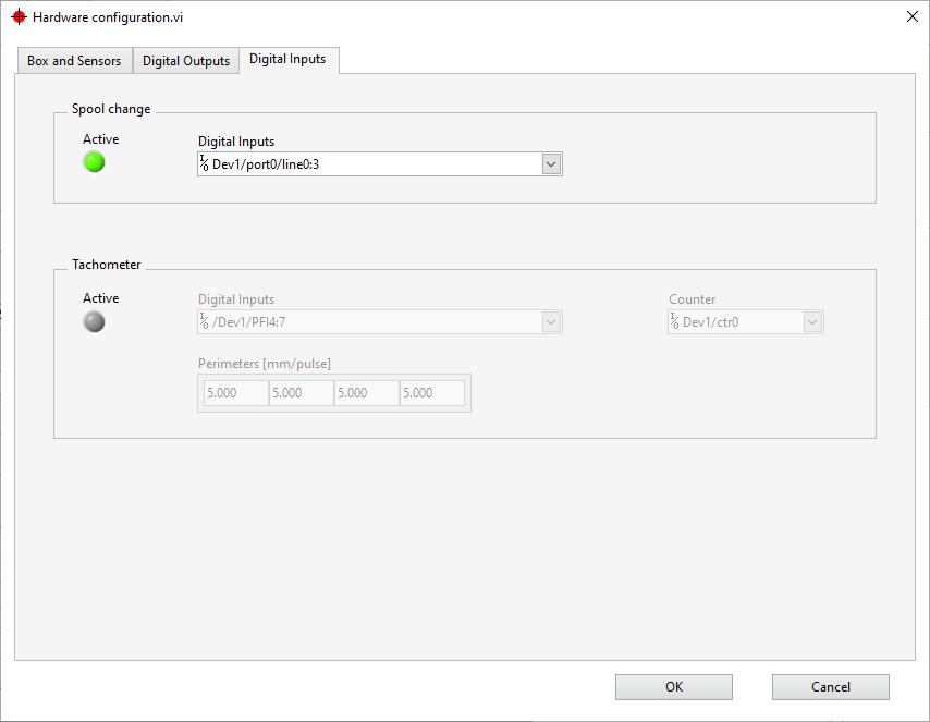
Figure 1: Settings for Digital Inputs. In this case the DIs for spool change are activated, while those for the wire velocity are not.
The digital inputs can be used to signal a spool change (i.e. start and stop a measurement) and, with a special hardware wheel, to measure the wire velocity. In this case we want to set the DIs for spool change, so we refer to the upper box in Figure 1.
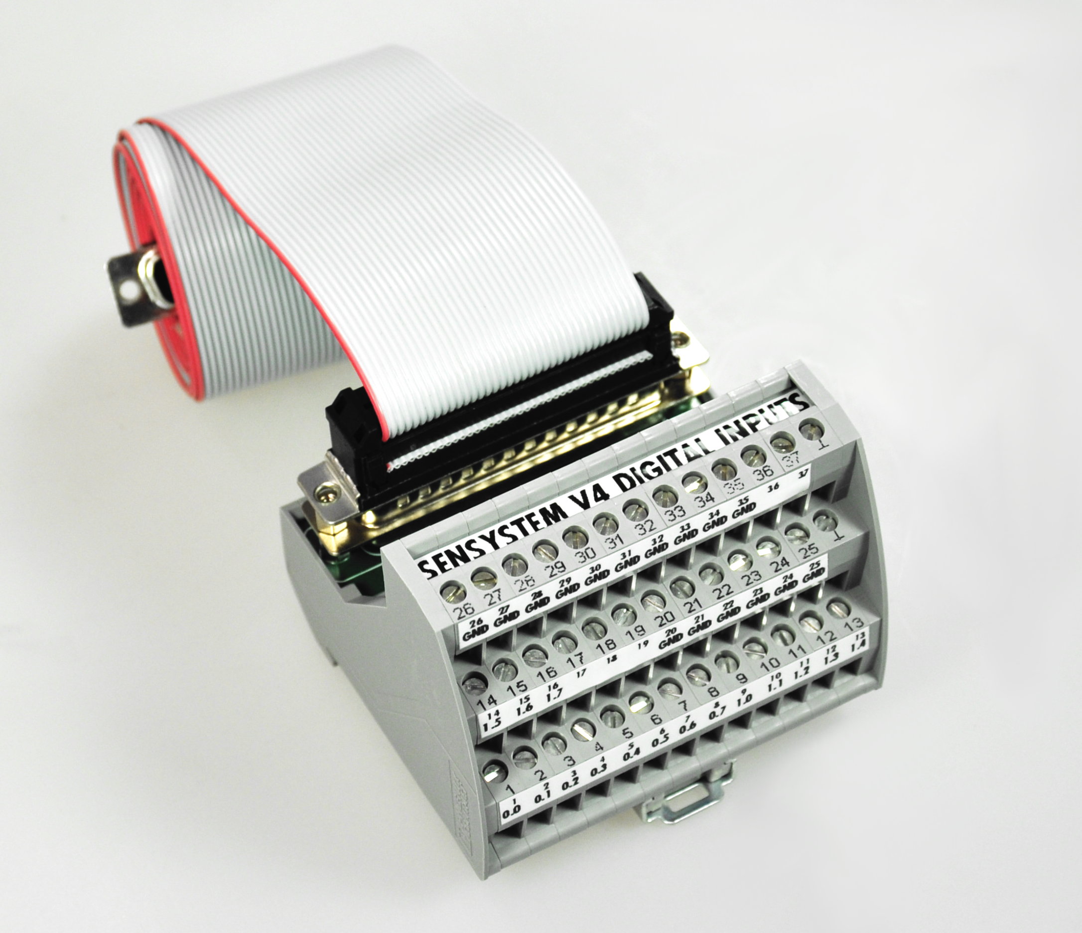
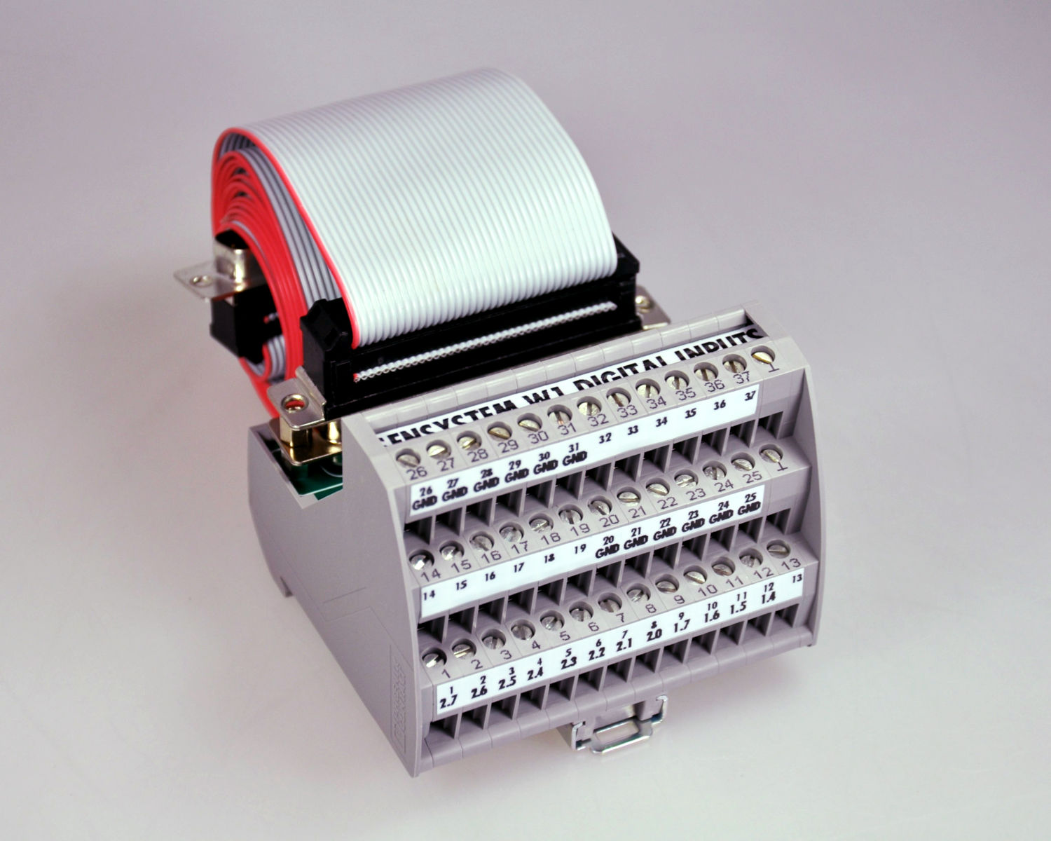
To use the digital inputs, activate them in the Settings dialog (Figure 1). The field Digital Inputs on the left specifies the pins for the spool change signals for all lines. It is recommended not to change this field and use it only to identify the pins on the break-out (Figure 2). In the normal case there is one pin for each sensor connector on the Sensystem box. Let's consider an example: A Sensystem Standard has four connectors C1, C2, C3, C4; the connectors C1 and C2 connected each to a sensor; the Digital Inputs field states Dev1/port0/line0:3. Press Start all to start the Sensystem, which will wait for a DI going to high (nominally +24 V against the GND pins, actually 18 .. 28 V). Changing pin Dev1/port0/line0 or 0.0 as it is labeled on the break-out, to high starts the measurement of the first line (sensor C1). Pin 0.1 starts the measurement of the second line (sensor C2) when it is going to high and stops the measurement when it is going to low. Which pins are GND and to what pin number (1 to 37) of the D-Sub-37 flat connector they correspond can be seen on the break-out (Figure 2).
To make the change permanent save the settings.
  |
|
Figure 2: Break-out with 37-pin D-Sub flat cable of the Sensystem V4 (left) and W1 (right).
|
  |
|
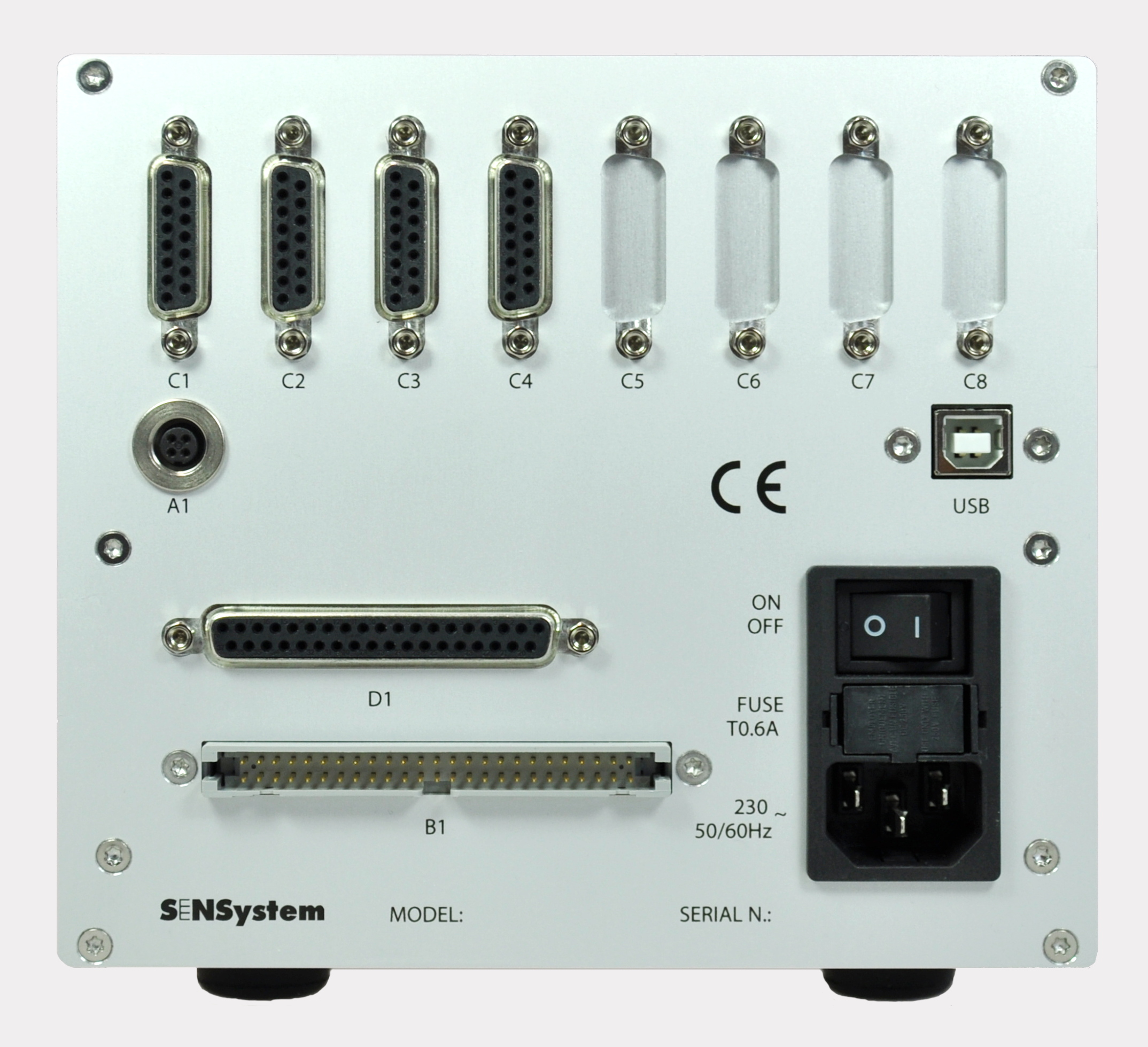
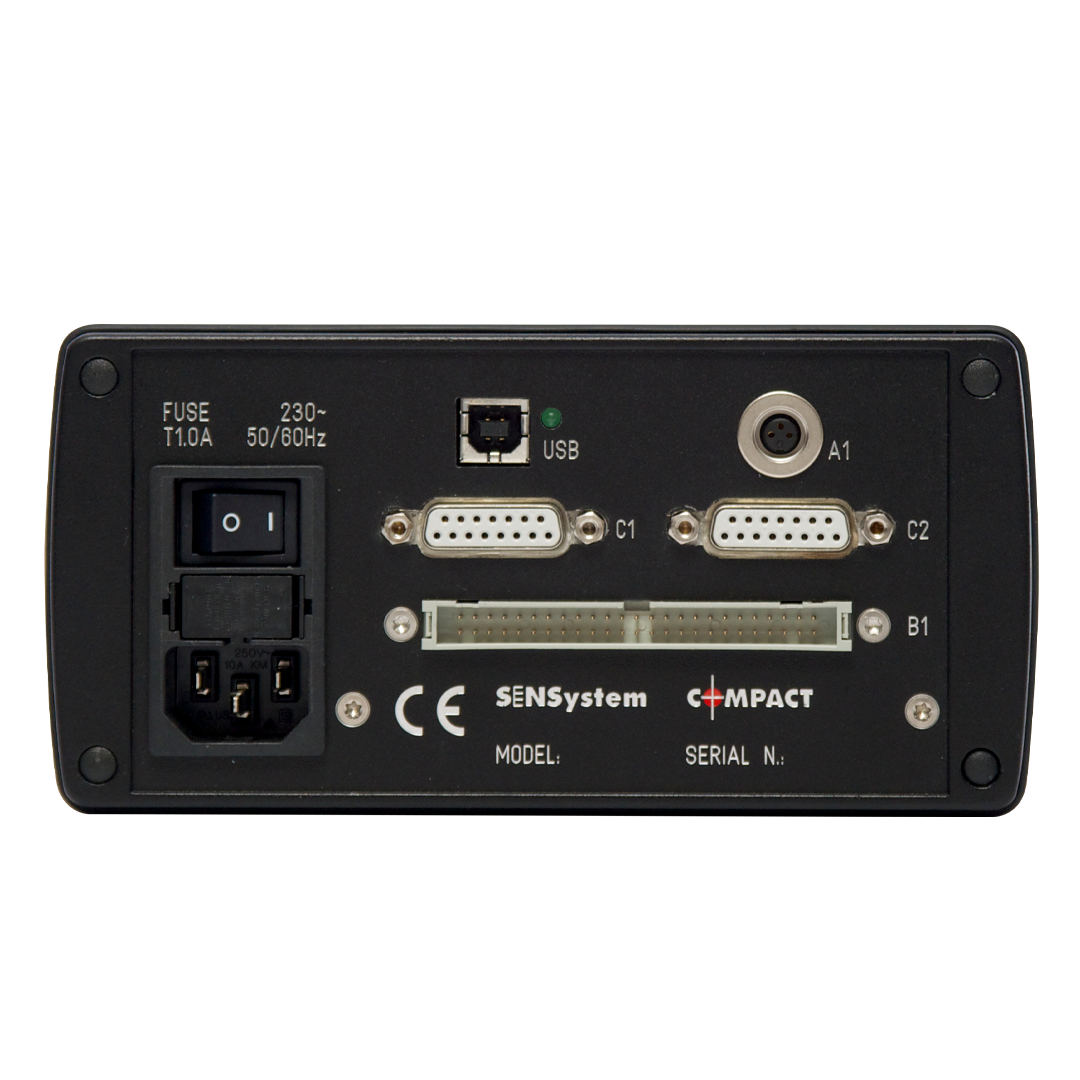
Figure 3: Rear of Sensystem Standard (left) and Compact (right).
|
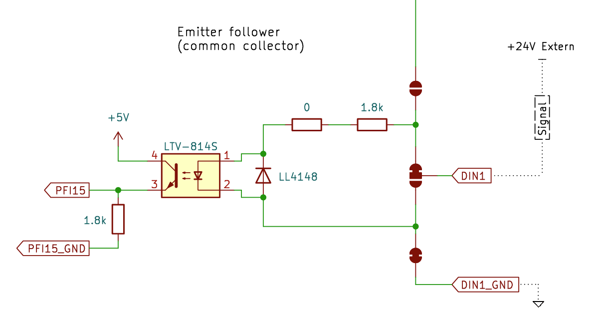 Figure 4: Schematics of the opto-coupler used inside the Sensystem |
Hardware connection
For the Sensystem Standard the signal goes into connector D1 (D-Sub-37). For the Sensystem Compact into connector B1 (ICD-50). These connectors are galvanically separated from the rest of the electronics so that no noise is transmitted to the sensitive electronics. The standard input configuration is an Emitter-Follower, see Figure 4. For reliably reading, the Start/Stop DI signal has to stay in one state for at least 2 s (Sensoft Multiline 1.3.1 and later relax this to 2/Update rate [Hz]).
Tachometer
Apart from spool change, DIs can be used to give Sensoft the velocity of the filaments.
Also here, the tachometer DI functionality has to be activated in the software settings (Figure 1) and the number of defined Digital Inputs should match the number of sensor heads (active and inactive) available in the configuration.
The frequency of the tachometer must be between 2 Hz and 10 kHz (with hardware prior to June 2023 between 2 Hz and 1 kHz) and it must be higher than Update rate [Hz]. The field Update rate [Hz], located on page Settings, is 1 Hz by default, but can be increased up about 10 Hz if a swift reaction time is needed, e.g. for a marker.
Each second the velocity of one line is measured. Only if the velocity of that line changed, it is updated. Thus setting the velocity by Digital Inputs is compatible with other ways of setting the velocity (i.e. manual and by OPC UA).
Example: For a Sensystem Compact on Dev1 with two sensors you could enter /Dev1/PFI2:3 . Note that these are the same ports as the Dev1/port0/line2:3, which cannot be used any more as Spool change Digital inputs. Field Spool change Digital Inputs should therefore be set to Dev1/port0/line0:1
| Sensystem Compact | PFI0:3 = port0/line0:3 |
| Senystem Standard | PFI0:7 = port1/line0:7 PFI8:15 = port2/line0:7 |
Grouped or inactive sensors
In the field Digital Inputs include every possible physical sensor (i.e. every row in the Box and Sensors page of Figure 1), even if the sensor is not attached, not activated or grouped with another one. This allows to activate and deactivate sensors without having to change the hardware wiring. Table 2 shows the total number of digital outputs of the different Sensystem models. If there are not enough digital outputs, you can assign a dummy port to the "unused" connectors. The "unused" connectors are those whose Line name does not appear as a line name in the main page of Sensoft Multiline, either because they are set as inactive in the Box and Sensors page, or because they are not the first sensor of a sensor group. E.g.: A Sensystem W1 has 8 mono-axial PXS sensors grouped into 4 bi-axial sensors (grouped are C1 with C2, C3 with C4, C5 with C6 and C7 with C8, and all connectors are connected). We want to use both Spool change DIs and Tachometer DIs. Although we really use only 8 DIs (for each of the 4 virtual sensors one for spool change and one for the tacho), we must specify 16 DIs (for each of the 8 physical sensors one for spool change and one for the tacho). Since we only have 12 DIs available, we choose to use 8 for start/stop and 4 for the tacho. For Spool change we use the Digital Inputs Dev1/port2/line0:7 . The wires must be connected to the pins 2.0 (= port2/line 0), 2.2, 2.4 and 2.6 . In the field Tachometer Digital Inputs we must include some dummy DIs at the places of the "unused" C2, C4, C6 and C8. For C2 we choose to just repeat the DI of C1, and so forth for the other connectors. The Tachometer Digital Inputs field thus could read /Dev1/PFI4, /Dev1/PFI4, /Dev1/PFI5, /Dev1/PFI5, /Dev1/PFI6, /Dev1/PFI6, /Dev1/PFI7, /Dev1/PFI7 or the equivalent but slightly compacter /Dev1/PFI4, /Dev1/PFI4:5, /Dev1/PFI5:6, /Dev1/PFI6:7, /Dev1/PFI7 . The wires must be connected to the pins 1.4 (= PFI4 = port1/line4) to 1.7 .
| Model | Number of DIs | DIs |
| Compact | 4 | port0/line0:3 |
| V3 | 16 | port0/line0:15 |
| V4, V6 | 16 | port0/line0:7, port1/line0:7 |
| W1 | 12 | port2/line0:7, port1/line4:7 |