Digital Outputs (DO) in Sensoft Vision
Applies to
Sensoft Vision 1.7.2 and later
For older versions see this page
Question
Can I get a digital output signal when a fault is detected? Or when an alarm is raised? Where would I connect the wires?
Answer
SenSystem Vision can output a voltage pulse when a defect is detected. It can also output a voltage (pulse or continuous) when a warning or an alarm is raised.
Software settings
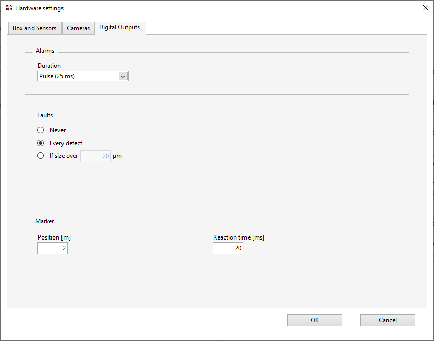
Figure 1: Settings for Digital Outputs.
The settings for the digital outputs (DO) are shown in Figure 1. To go there, on page Settings click on Show advanced settings and then on Hardware settings.... In the appearing dialog window go to page Digital Outputs.
There are two types of Digital Outputs (DO):
- Fault DO: A pulse for every fault.
- Warning DO and Alarm DO: A pulse or dc voltage when there is an alarm or warning. They work only with Advanced Criteria.
Fault, Warning and Alarm DOs are output on separate pins, see below. For using Warning DO and Alarm DO, you just have to write warning resp. alarm criteria. These criteria can be written in the Criteria field on the Main page. If it is not visible, please click with the right mouse button on the Threshold [µm] field and select Use Advanced Criteria from the context menu.
In the upper part of the DO settings (Figure 1) you set the form of the Alarm and Warning DO:
- Off - Deactivated.
- Until wire good again - The DO signal is on until no criteria is fulfilled (or more precisely: for warning DO no warning criteria, for alarm DO no alarm criteria). Typical use: Warning lamp or siren, signaling to the operator to control the process.
- Until the end of the measurement - The DO signal is on until the end of the measurement (i.e. the end of the spool). Typical use: Warning lamp or siren, signaling to the operator to discard the spool.
- Pulse (25 ms) - The DO signal is on for 25 ms. The pulse is delayed until the defect arrives at the Marker specified below. Typical use: Trigger a marker.
In the middle part you set when to activate the Fault DO, which is always pulsed (25 ms duration). For precise defect marking or cutting, all pulsed DOs are synchronized to the time when the defect passes the marker. Its distance from the sensor can be set in the bottom part. The minimum distance for the marker depends on the wire velocity and the output type. If you are marking faults the minimum marker position is negligible (marker reaction time times wire velocity). If you are marking alarms or warnings it is about 2 s * wire velocity.
To make the change permanent save the settings.
Hardware connection
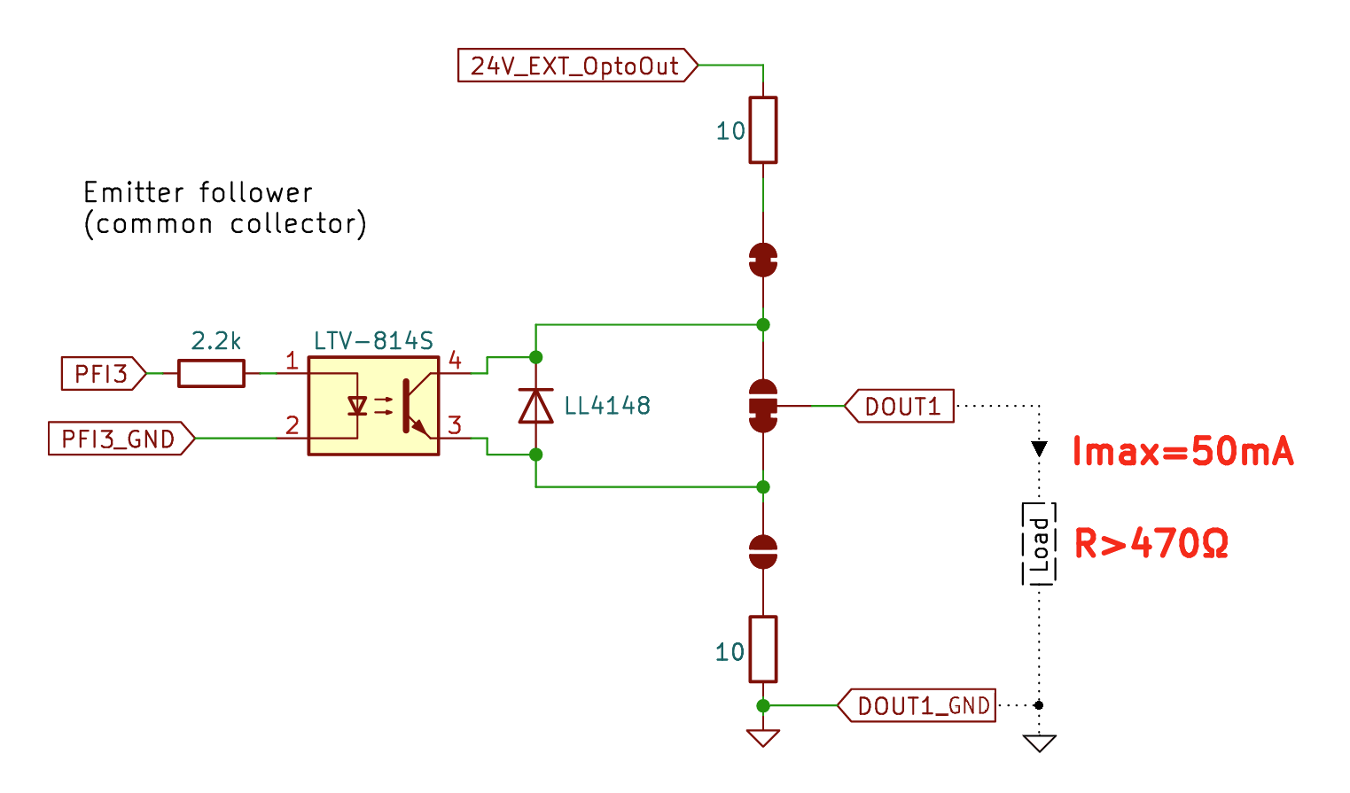
Figure 2: Schematics of the DO hardware.
The signal comes out of connector DO (ICD-50). The connector DO is galvanically separated from the rest of the electronics so that no noise is transmitted to the sensitive electronics. This means that the 24 V voltage for connector DO has to be supplied by an external power supply. The external 24 V power supply can be a switching power supply and should be connected to connector A1 on the rear panel of the Network controller (see the specifications for the A1 connector). The Output configuration is by default Emitter-Follower. The load should be greater than 470 Ohm, and the drawn current should not exceed 50 mA. For pulsed DOs, if the load has high impedance, you may want to shorten the fall-down time by adding a pull-down resistor of 10 kΩ in parallel (in Figure 4 between DOUT1 and DOUT1_GND).
| Pin of connector DO | Name | Description |
| 1 | Fault | +24 V versus Ground for 25 ms when a defect occurs |
| 2 | Ground | All ground pins are equal |
| 3 | Warning | +24 V versus Ground when a Warning criterion is fulfilled |
| 4 | Ground | |
| 5 | Alarm | +24 V versus Ground when a Alarm criterion is fulfilled |
| 6 | Ground |
Specifics of pulsed DOs
All pulsed DO are synchronized, i.e. they are emitted when the defect is at the marker (minus a distance tr * v corresponding to the reaction time tr of the marker times the wire velocity v at the time of the defect detection by the sensor). Pulses arrive even after the end of the measurement, but not if another measurement is started. The wire velocity is expected not to drop too much (not below v/2) before the defect arrives to the marker. The Fault DO is scheduled by the FPGA of the sensor, meaning that it is very precise and reliable. The Warning and Alarm DO are scheduled by the PC: They are similarly precise but the PC must remain responsive. The allowed lag depends on the marker distance d and the wire velocity: The allowed lag is d/v - tu, where d/v is the time it takes the defect to go to the marker and tu is the update time (a settable parameter, by default 1 s). So if the marker is 2 s away, the allowed lag is 1 s. This is fine most of the time, but it is clear that allowing lags of 2 s or 3 s increases the reliability further. You notice lags if the position indicator on page Main does change. Lags of over 2 s are really rare.
The following table details the behavior and the most important border cases.
| Case | Fault DO | Warning and Alarm DO |
| Typical precision | 5 mm | 5 mm ± 25 ms * v |
| Defect does not arrive at the marker, or much too late | If the defect does not arrive at the marker within twice the expected time, the pulse is aborted, i.e. not emitted. In formulas: Abortion time = 2*d/v - tr + 0.1 s. | |
| Defect arrives at the marker after end of measurement | Pulse is emitted, but only if no new measurement has been started | |
| Defect arrives at marker too early (before DO is scheduled) | Practically impossible | DO pulse emitted as soon as possible. Solved by larger marker distance |
| PC lags (e.g. 2 s) | No problem | If allowed lag < 2 s (i.e. if marker distance < 3 s * v): DO pulse emitted as soon as possible. Else: No problem |
| Defects in the first second of the measurement | No problem | In the first second the allowed lag is reduced by 1 s |
| Defects are very near (e.g. 10 defects in 100 ms) | One pulse of 10*25 ms | 2 pulses of 25 ms (all defects within 50 ms are grouped into one pulse) |
| Daylight saving time change | No problem | No problem |