
Start/Stop by Digital Input (DI)
Applies to
Sensoft Vision
Issue
Where do I connect the wires for automatically start and stop measurements in Sensoft Vision?

Figure 1: Schematics of the DI hardware.
Hardware connection
You can use Digital Inputs (DI) to start and stop measurements. The required DI signal is a dc signal that goes to +24 V for starting the measurement and returns to ground when you want to stop the measurement. The Input configuration is by default Emitter-Follower, see Figure 1. Also when using digital inputs to start/stop measurements, you can still start/stop the measurements manually by clicking the Start/Stop button in Sensoft Vision.
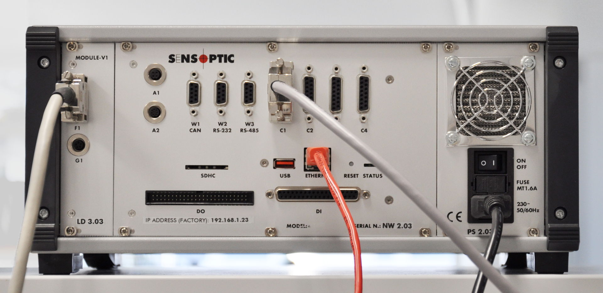
Figure 2: Back panel of the Sensystem Network with connectors DI.
Sensystem Network with PXL
Connect the wires to the following pins of connector DI on the SenSystem Network, Figure 2:
- Pin 5: Start/Stop signal
- Pin 26: Ground
The connector that goes into connector DI of the SenSystem Network is a 37 pin male D-SUB connector. We offer a set with cable and screwable break-out.
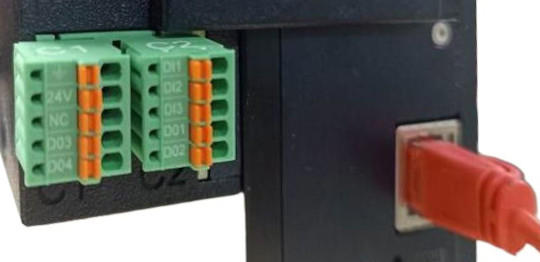
Figure 3: PXT sensor: Digital Input/Output connector.
PXT
Connect the digital input signals to the green connectors on the camera module next to the PXT sensor, see Figure 3.
| Pin of C1/C2 | Name | Description |
| ⏚ | Ground | Ground of Start signal |
| DI1 | Start | Measurement Start/Stop (+24 V versus ⏚) |