Measuring at rounded corners of rectangular wires
Applies to
Sensoft Multiline 2.1 and later
Issue
I need to detect blisters also in the corners of a rectangular wire. Can I do this?
Solution
Yes. You need additional measuring axes. Beyond the two axes measuring the defects on the faces of the rectangular wire (let's call them x and y), you need at least two additional axes looking at the corners (let's call them c1, c2, ..).
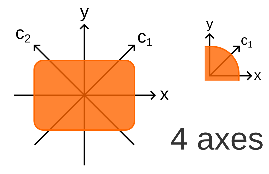 Figure 1: Corner inspection with 4 axes. The axes have a rotational offset of 45°. The inset shows the axes aligned with the center of the corner. |
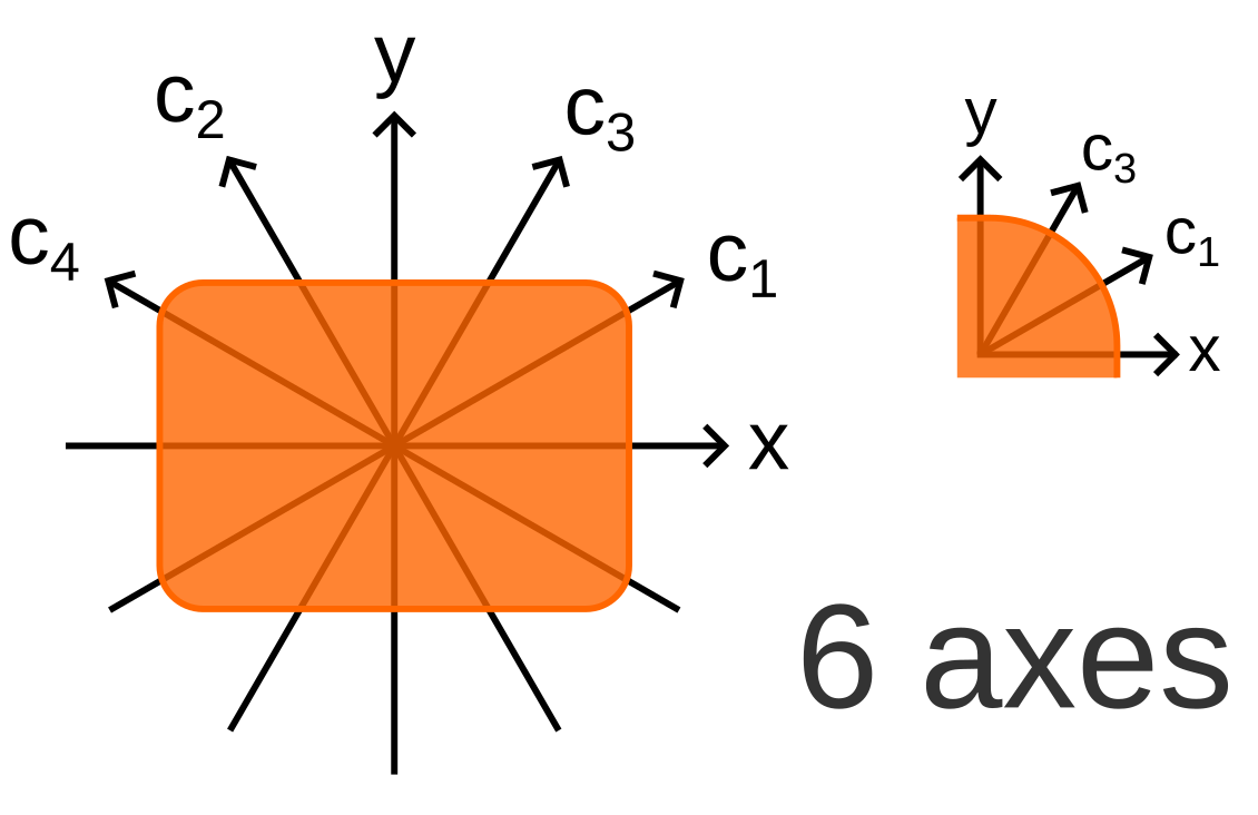 Figure 2: Corner inspection with 6 axes. The axes have a rotational offset of 30°. |
 Figure 3: Corner inspection with 4 axes. How large a hemisphere blister appears to a sensor with 4 axes, as a function of its position on the corner radius. As corner radius 480 um is assumed. The colors correspond to different blister heights. |
 Figure 4: Corner inspection with 6 axes. How large a hemisphere blister appears to a sensor with 6 axes, as a function of its position on the corner radius. As corner radius 480 um is assumed. The colors correspond to different blister heights. |
The number of axes required depends on the specifications that must be met. Since with round surfaces it is inevitable that there are blind zones, it is harder to achieve a certain lump threshold in the corners than on the flat surfaces. Ideally you should negotiate with the end customer that the threshold for corner defects applies along the measuring axes (e.g. at 45° if you use 4 axes). Defects on other positions need to be a bit larger to be detected. This is standard procedure with round wires, and allows you to use the same thresholds of the specs in your criteria. Figures 3 shows that for a corner radius of 480 μm in the worst case defects have to be 36 μm larger to be detected with 4 axes. Figure 4 shows with 6 axes in the worst case they have to be 16 μm larger. With a corner radius half as large, these numbers would be also half as large. Alternatively you can negotiate that defects on the corners have a higher threshold than the defects on the flats, e.g. 60 μm instead of 30 μm on the flats. In this case you should set the threshold lower than the specs, for 480-μm-corners at 24 μm if you have 4 axes resp. 44 μm if you have 6 axes.
Note that 4 axes are much more convenient to arrange than 6 axes: With 4 axes, c1 and c2 can be measured sliding in a PXL sensor parallel to its slit and body.
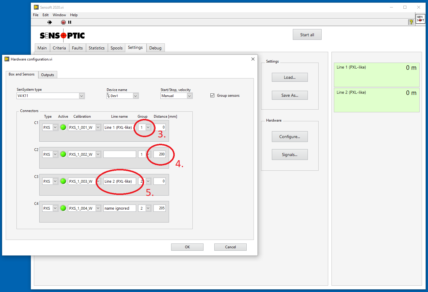
To configure the system for measuring at corners, you are welcome to contact us, so we do it together. The steps involved are:
- If the additional sensors are connected to a separate Sensystem, add another box to your configuration.
- Group the sensors that measure the same wire. The sensor on the lowest connector is the one that measures the x-axis. In this example with mono-axial PXS sensors, the one on connector C1 is the x-axis, the one on C2 the y-axis and eventual others (e.g. on connectors C1 and C2 of Box 2) will be the corner axes c1 and c2. In another example with three bi-axial PXL sensors, the one on the lowest connector will measure the x and y axes, the next PXL c1 and c2 and the last c3 and c4.
- If you have a marker, the distance value on page Digital Outputs is calculated from the center of the last physical sensor (the one that has the largest value of Distance [mm] on page Box and Sensors.
- Exit the configuration dialog window by pressing with OK.
- In the Criteria field on page Criteria you can use the following names:
Name Meaning LumpFault on x, y, c1, c2, ... i.e. detect faults on the flats and on the corners LU xyFault on x or y, i.e. detect only faults on the flats LU cornerFault on c1, c2, ... i.e. detect only faults on the corners Of course
Neck-down,NE xy, andNE cornerare also valid. Examples:Warning if Lump > 30 μmdetects faults anywhere.Warning if LU corner > 30 μmdetects faults if they are on a corner, but ignores them if they are on a flat surface. - Set the nominal diameter for each axis. If the field Nom. diameter [μm] shows only one value, click it with the right mouse button an select Use different diameters for x and y. You can also set the diameters via OPC UA.
With 4 axes the diameters are [Width, Height, D45, D45], where .
.
With 6 axes they are [Width, Height, D30, D60, D60, D30], where and
and  .
. - Remember to save the settings.