Digital Outputs (DO) in older Sensoft Multiline
Applies to
Sensoft Multiline 1.2.4 and before. For current software see this page.
Question
Can I get a digital output signal when an alarm is raised? Or when a fault is detected? Where would I connect the wires?
Answer
SenSystem does output a voltage when a warning or an alarm is raised. It does not output a voltage when a fault is detected, but you can set criteria to raise a warning at every fault, e.g. "Warning if lump > 100 µm".
Software settings
To configure digital outputs (DO) click on Configure... on page Settings and then change to the tab Digital Outputs, see Figure 1.
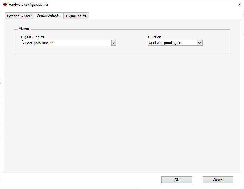
Figure 1: Settings for Digital Outputs
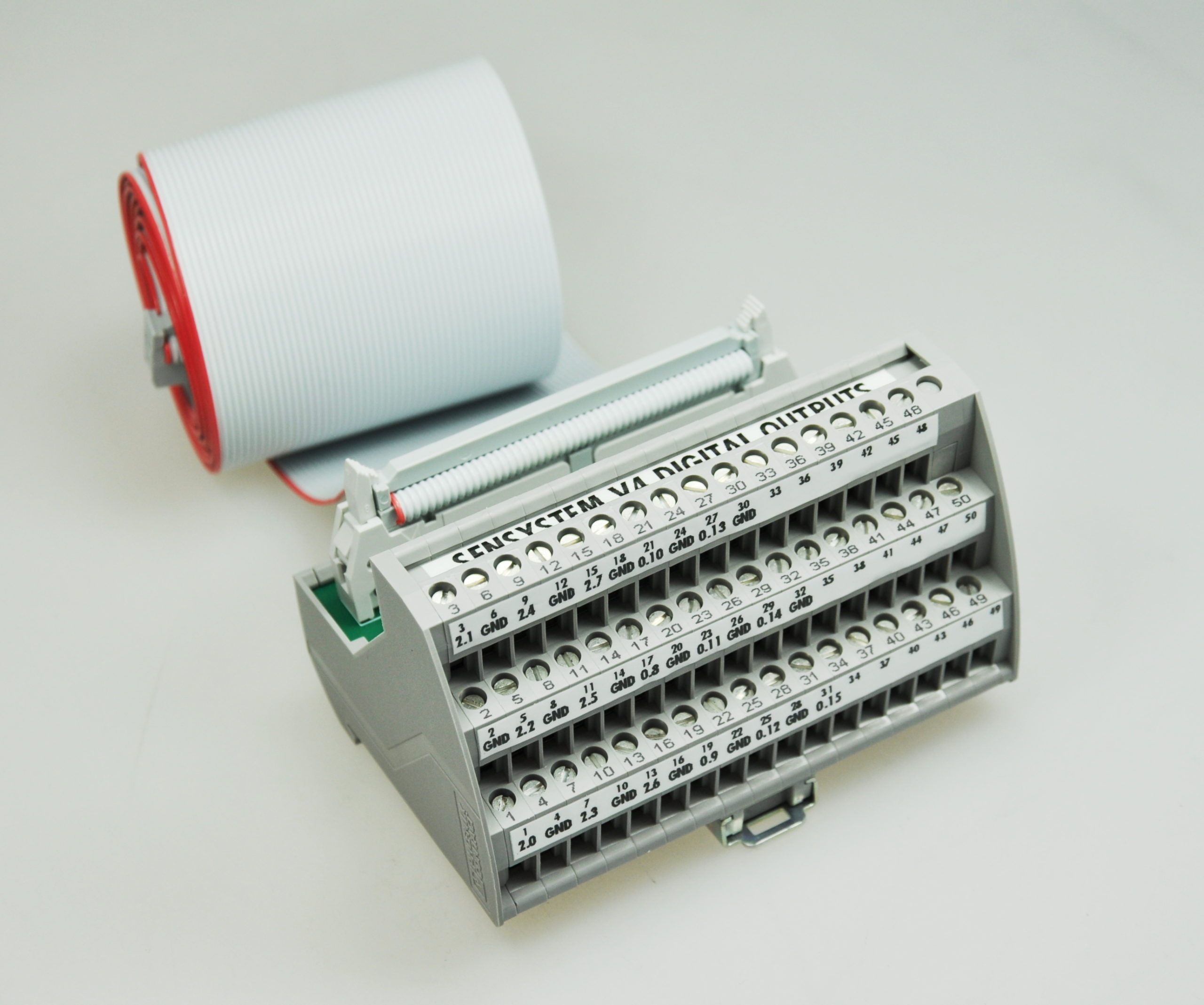
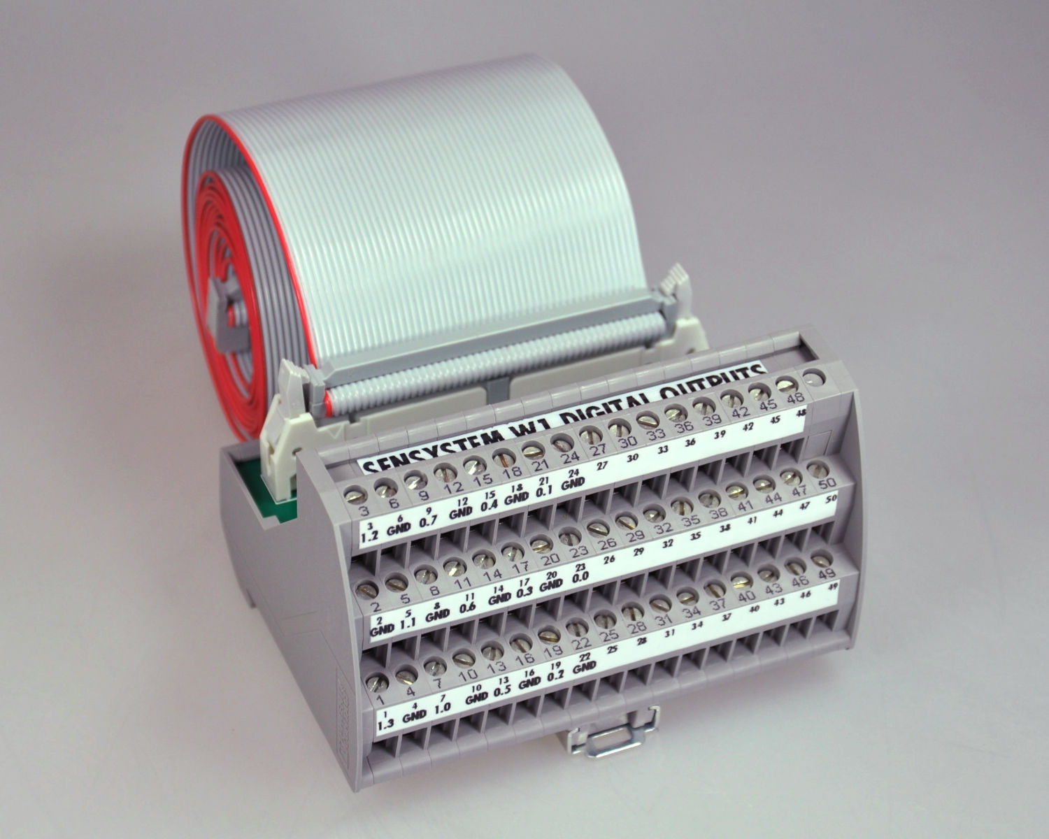
The field Digital Outputs on the left specifies the pins of the warning and alarm outputs. It is recommended not to change this field and use it only to identify the pins on the break-out (Figure 2). In the normal case there are two pins for each sensor connector on the Sensystem box, one for warnings and one for alarms. To see how they are ordered let's consider an example: A Sensystem Standard has four connectors C1, C2, C3, C4; the connectors C1 and C2 connected each to a sensor; the Digital Outputs field states Dev1/port2/line0:7. Then pin Dev1/port2/line0 or 2.0 as it is labeled on the break-out goes to +24 V when the sensor connected to C1 raises a warning. Pin 2.1 goes high (i.e. +24 V against any of the GND pins) when the sensor connected to C1 raises an alarm. Pin 2.2 goes high when the sensor connected to C2 raises a warning and so on. Which pins are GND and to what pin number (1 to 50) of the IDC-50 flat connector they correspond can be seen on the break-out (Figure 2).
  |
|
Figure 2: Break-out with IDC-50 flat cable for Sensystem V4 (left) and W1 (right).
|
  |
|
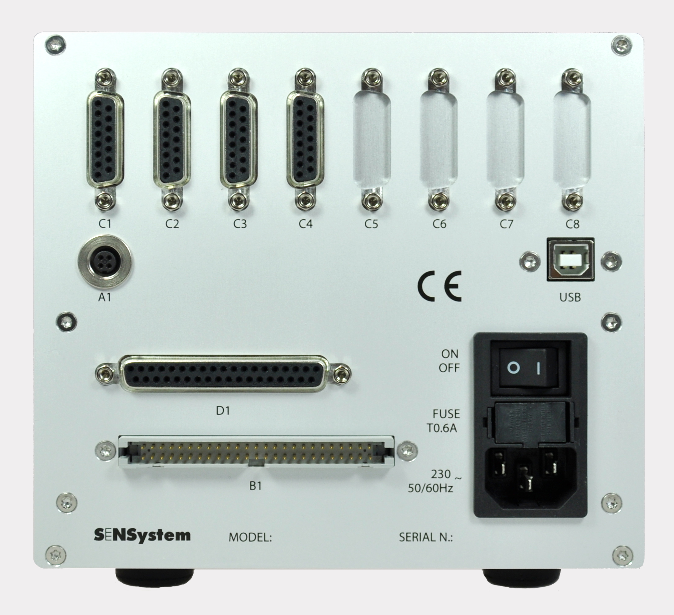
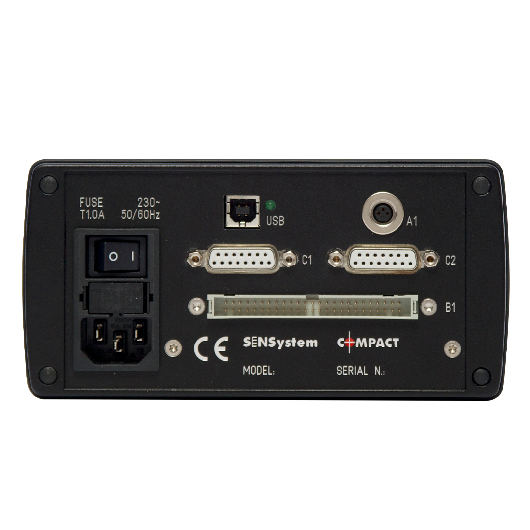
Figure 3: Rear of Sensystem Standard (left) and Compact (right).
|
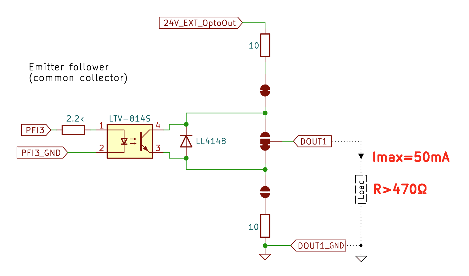 Figure 4: Schematics of the opto-coupler used in the Sensystem. |
By default the warning and alarm DOs stay high until no warning (resp. alarm) criterion is met, i.e. the wire is good again. You can change this with the field Duration, which has the following choices
- Until wire good again - The DO signal is on until no Criteria is fulfilled (or more precisely: for alarm DO: no alarm criteria, for warning DO: no warning criteria). Typical use: Warning lamp or siren, signaling to the operator to control the process
- Until the end of the measurement - The DO signal is on until the end of the measurement (i.e. the end of the spool). Typical use: Warning lamp or siren, signaling to the operator to discard the spool
- Pulse (25 ms) - The DO signal is on for 25 ms. Typical use: Trigger a marker or some other external device. Note: The pulse has some delay (typically 1 s) from the fault triggering the alert, meaning that a marker cannot be used if the wire runs at high speed.
To make the change permanent save the settings.
Hardware connection
The signal comes out of connector B1 (ICD-50). The connector B1 is galvanically separated from the rest of the electronics so that no noise is transmitted to the sensitive electronics. This means that the 24 V voltage for connector B1 has to be supplied by an external power supply. The external 24 V power supply can be a switching power supply and should be connected to connector A1 on the rear panel of the Sensystem (see the specifications for the A1 connector). The output configuration is by default Emitter-Follower, see Figure 4. The load should be greater than 470 Ohm, and the drawn current must not exceed 50 mA.
Reaction time
There is a delay of approximately 1/Update rate [Hz] between the fault raising the alert passes the sensor and the switching of the DO. The field Update rate [Hz] is on the page Settings and by default is 1 Hz. The resulting delay of approximately 1 s is no problem for a siren or lamp, but can be too long for a marker. In Sensoft Multiline 1.2 and later Update rate [Hz] can be increased to about 10 Hz, unless there are many sensors (i.e. more than 16 sensors). Feel free to contact us if you consider increasing the update rate, we are happy to check your settings.
Grouped or inactive sensors
In the field Digital Outputs include every possible physical sensor (i.e. every row in the Box and Sensors page of Figure 1) in the port list, even if the sensor is not attached, not activated or grouped with another one. This allows to activate and deactivate sensors without having to change the hardware wiring. The table below shows the total number of digital outputs of the different Sensystem models. If there are not enough digital outputs, you can assign a dummy port to the "unused" connectors. The "unused" connectors are those whose Line name does not appear as a line name in the main page of Sensoft Multiline, either because they are set as inactive in the Box and Sensors page, or because they are not the first sensor of a sensor group. E.g.: A Sensystem W1 has 8 mono-axial PXS sensors grouped into 4 bi-axial sensors (grouped are C1 with C2, C3 with C4, C5 with C6 and C7 with C8, and all connectors are connected). Although we will use only 8 DOs (one for warnings and one for alarms, for each of the 4 virtual sensors), we must specify 16 DOs (two for each of the 8 physical sensors). Since we only have 12 DOs available, we include some dummy DOs at the places of the "unused" C2, C4, C6 and C8. For C2 we choose to just repeat the DOs of C1, and so forth for the other connectors. The Digital Outputs field thus could read Dev1/port0/line0:1, Dev1/port0/line0:1, Dev1/port0/line2:3, Dev1/port0/line2:3, Dev1/port0/line4:5, Dev1/port0/line4:5, Dev1/port0/line6:7, Dev1/port0/line6:7 or the equivalent but slightly compacter Dev1/port0/line0:1, Dev1/port0/line0:3, Dev1/port0/line2:5, Dev1/port0/line4:7, Dev1/port0/line6:7 .
| Model | Number of DOs | DOs |
| Compact | 4 | port1/line0:3 |
| V3 | 16 | port1/line0:7, port2/line0:7 |
| V4, V6 | 16 | port0/line8:15,port2/line0:7 |
| W1 | 12 | port0/line0:7, port1/line0:3 |