
Fault clustering
Applies to
Sensoft Multiline
Sensoft Vision
Question
I would like to count a cluster of blisters as one fault instead of many. My specs allows this if the faults are less than 5 cm apart. Is this possible?
Answer
Yes. The answer here applies to Sensoft Vision, and to Sensoft Multiline with Sensystem type K12 (i.e. when the wire velocities are < 100 m/min). Sensoft Multiline with Sensystem type K2 (for high wire velocity) automatically clusters faults in the cm range.
How to enable clustering in Sensoft Multiline
To enable fault clustering for LU x, LU y, Lump and Neck-Down:
- Open the .ini configuration file in a text editor.
It is most probably located inDocuments\LabVIEW Data\Sensoft\Config Data\Configurations Multiline. An easy way to open it in a text editor is to click con the button Load... on page Settings, click with the right mouse button on the file and select Open with > - Replace the
All custom sensorsblock (i.e. all lines starting with "All custom sensors") with the text in this file. Note: the file contains µ signs for microns. To retain them you have to save and open it, copy & paste mangles them up - Set the desired clustering range. By default, i.e. in the file linked just above, the clustering range is 0.1 m. To change it, change the value in all the lines
All custom sensors *.Max fault length \5Bm\5D = "0.1" - Assert that you are using OPC UA and that there are at least 4 custom sensors per line. This is done easiest in the config file by checking that slightly above the All custom sensors block there are the lines
Boxes 0.OPC parameters.Custom sensors per line = "4"Comm = "OPC UA"
How to enable clustering in Sensoft Vision
- On page Settings click on Show advanced settings
- Set Hysteresis [µm] to 15000. To do this you must first remove the checkmark near Auto
- Set Max fault length [mm] to the desired clustering range
- You may want to save the settings
How it works
A fault starts when the the signal measuring the diameter variation goes over a specified Threshold. It ends when the signal goes below Threshold minus Hysteresis, or if this does not happen, after Max fault length. This article describes why the hysteresis is needed in the presence of noisy signals. Figure 1 shows the default case, where the hysteresis is small compared to the threshold: Each blister in a cluster is counted as a fault and there is no clustering.
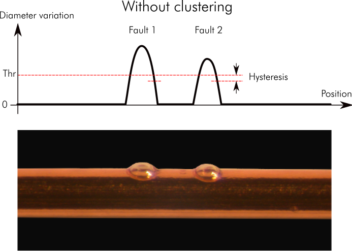
Figure 1: By default there is no clustering of faults. By default the hysteresis is set similar to the noise level, i. e. smaller than the threshold. Since a fault ends when the signal drops below Threshold minus Hysteresis, in this figure we record two faults.
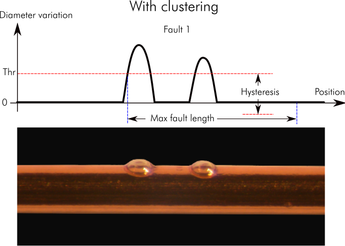
Figure 2: With clustering the hysteresis is basically infinity, the signal can never get below Threshold minus Hysteresis. The fault is processed after Max fault length has passed. Fault length is equal to the sum of the two blister lengths (i.e. where the signal is above threshold).
If now we set Hysteresis to a very large value (i.e. much larger than Threshold), then the fault always ends after Max fault length (Figure 2). The Fault length is defined as the length with signal above threshold. Therefore the length of the fault in Figure 2 is equal to the sum of the lengths of the two faults in Figure 1. The profile graph and the photo will be centered to the highest signal point.
What limits Max fault length?
- Camera: Max fault length should be smaller than the distance to the camera, and in addition provide some time for the photo scheduling. In Sensoft Vision the camera is about 45 mm after the sensor and the scheduling is fast. This limits Max fault length to about 30 mm. In Sensoft Multiline it adds Max fault length to the minimal distance the Crystal camera module can be positioned. How much this limits Max fault length depends on how precisely the wire velocity is known, but typically to about 50 mm.
- Marker: With clustering the minimum marker distance is Max fault length larger than without clustering. The minimum marker distance without clustering is explained in the DO (Multiline) or DO (Vision) page. Also, the marking range has to be larger than twice Max fault length plus reserve. In praxis the marker rarely limits Max fault length.
Caveats
- Fault length - In older software (up to Sensoft Vision 2.3.13 and Sensoft Multiline 2.4.1) when using clustering, fault length was intended as cluster length, i.e. from the start of the first fault in the cluster to the end of the last fault of the cluster. In even older software (up to Sensoft Vision 1.7.2 and Sensoft Multiline 1.2.4) the fault length was always the specified Max fault length.