Rectangular wire with Sensoft Vision
Applies to
Sensoft Vision
Practical aspects
-
The system has to be installed with the wire running in the right direction. The detection by the PXL sensor has to precede the capture of the image by the camera. If the wire runs from left to right, the encoder should be on the right side.

-
Ideally the system should be mounted with it's aperture looking downwards to avoid the dust entering in the measuring field. If this is not possible, the system may be mounted with the PXL sensor looking upwards.
-
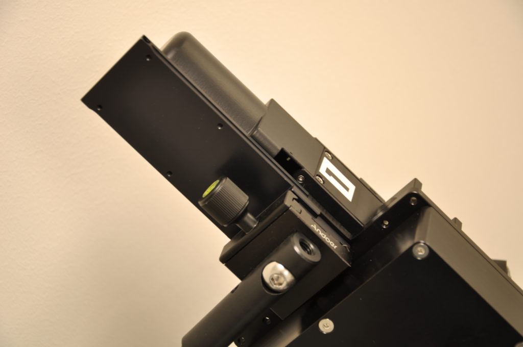
The fixation of the bracket has to be studied carefully before mounting the system to ensure that the arms are long enough. Because of the weight of the system the clamp of the arm may rotate even if fixed tightly. The clamp should be fixed so that it cannot rotate in the direction of the force due to the gravity.
-
The quick fixation clamp which holds the Sensor on the bracket has to be closed tightly as a vibration on the machine may make the sensor slipper depending on the mounting orientation.
-
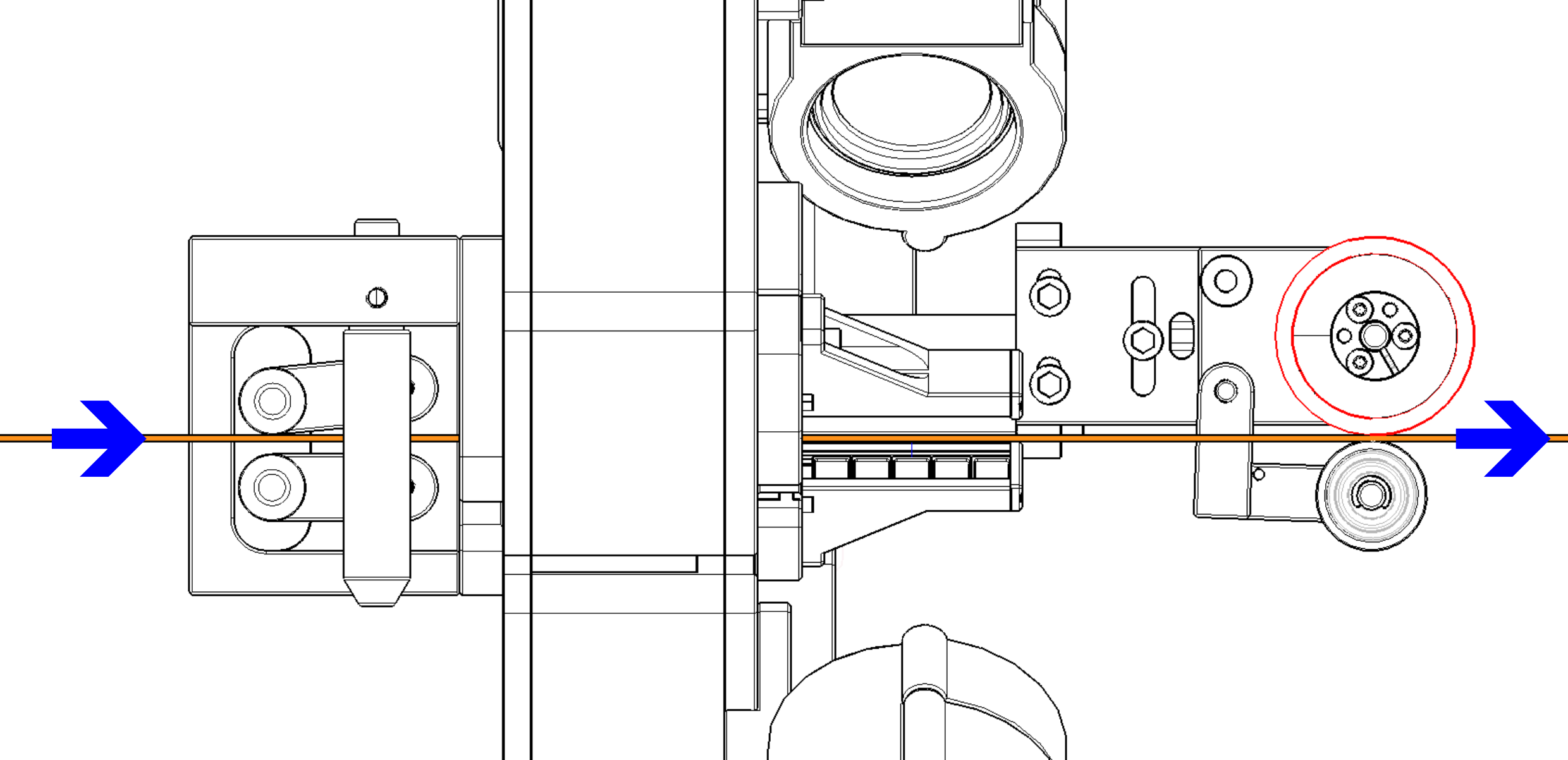
The external cylindrical guides should be removed before inserting the wire on the PXL measuring field. The aperture of the PXL is 5 mm. depending on the wire dimension the PXL aperture should be placed parallelly to the long dimension of the wire to make the insertion of the wire. The system should then be rotated of 45 degrees.This operation is delicate as in some cases the wire may get blocked on the guides and the forces involved are very important.
-
The fixation of the system in a good position and orientation is extremely important. The wire should run straight through the system along its axis. If it's not the case it may then have a cyclical torsion which should be avoided as much as possible.
-
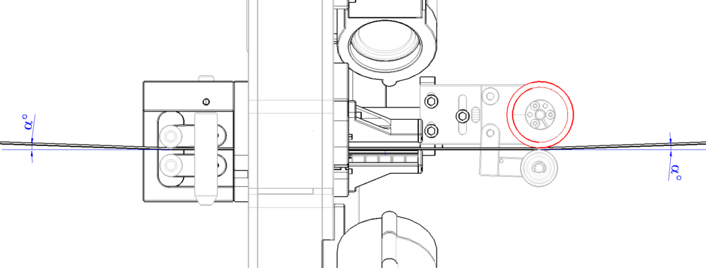
The system should be mounted so that there is an input and output angle a of the wire with respect to the horizontal cylindrical guide and the encoder. The counter-wheel of the encoder may not make a sufficient force to bend the wire and ensure a contact with the encoder. The contact should be guaranteed by this output angle of the wire with respect to the encoder wheel. The a angle should not be too high as depending on the thickness of the wire there may be an important curvature radius. For thick wires the wire may then be too near the border of the measuring slit.
-
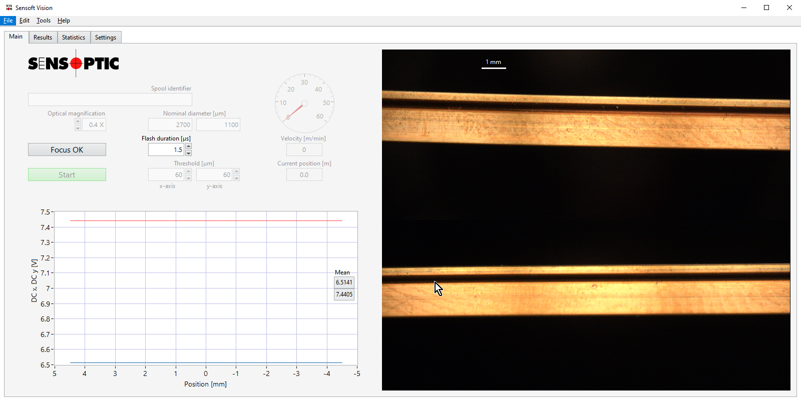
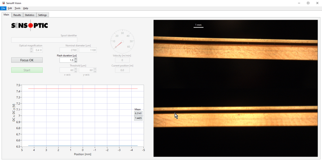
The system should be mounted so that the X and Y axes of the sensor are parallel to the main axes of the wire (Width and Height). When in focus mode by right clicking on the graph, the Voltage outputs of the PXL sensor (DC X and DC Y) can be shown continuously. These values are at it's maximum when the alignment is optimal. One may monitor theses values while mounting the system on the line to find the best alignment conditions. To show the voltage DC x and DC y values, when in "Focus adjustment" mode right click with the mouse on the image and select "Show signals". If the wire lies horizontally with respect to the encoder wheel (see point 15), the Y axis in red has a higher voltage value and a higher sensitivity to a torsion angle. For this reason it is better to look for the maximum of the Y axis value (below) when optimizing the wire orientation.
-
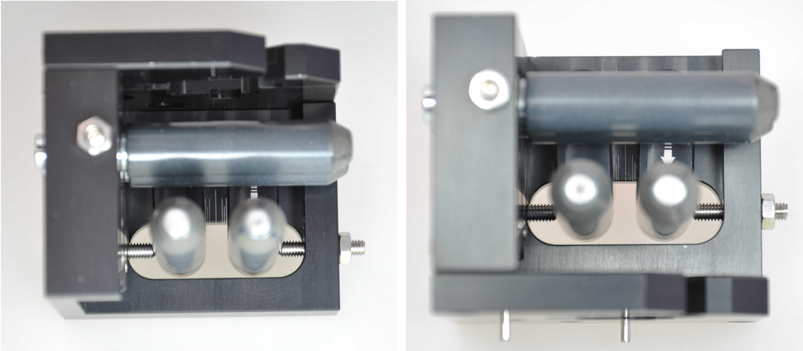
One should check that the wire is more or less centred on the image. The centring will depend on the position of the wire with respect to the guides and the encoder. In the cylindrical guides holder part a scale is engraved so that the alignment of the guides with respect to the optical centre can be visually checked. The guides should be centred with respect to the optical centre. Enough space between guides should be left so that the eventual defects can pass through. Ideally the wire should go straight between the vertical cylinders and should not touch these guides to prevent the torsion of the wire. The position range of the cylindrical guides can be limited with a stop screw and a bolt. These should be adapted depending on the customer wire dimensions range.
-
One should choose the right magnification of the Zoom objectives. Both optics of the dual camera system should have the same magnification and the same diaphragm aperture so that the aspect of the wire is similar in both images. The correct magnification should be set on the software.
-
Usually an aperture of 8 or 11 is used for the diaphragm. One should then play with the duration of the flash to get the right wire illumination.
-
When starting the measurement it is better to set a not too low threshold such as 50 um. Depending on the result and if no fault is detected in can be then reduced.
-
While measuring it is better no to change the criteria mode between Simple and advanced as this affects the counting of the faults.
-
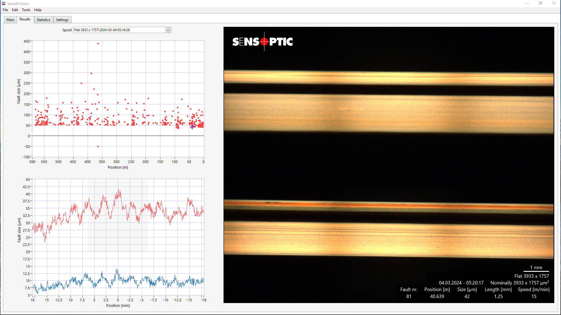
Long faults not clearly visible in the image and with a similar shape between X and Y may indicate a torsion of the wire.
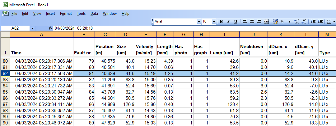
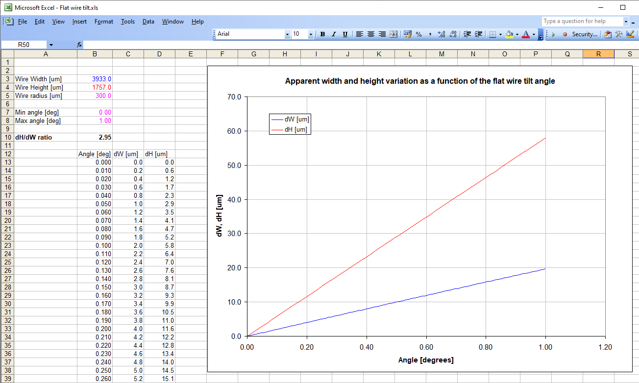
Given the dimensions of the wire (width and height) and it's radius it is possible to calculate the apparent diameter increase of it's dimensions as a function of the angle. This can be calculated by entering the values in the "Flat wire tilt.xls" Excel file. If the ratio between the shapes of the profiles Y/X matches the calculated theoretical ratio, there is a great probability that the wire is tilting.
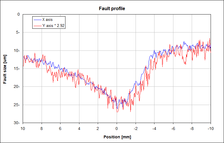
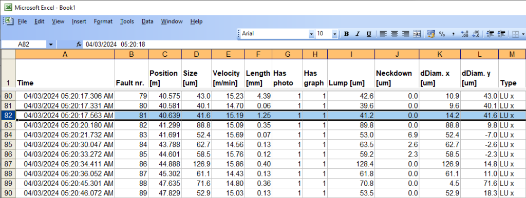
In the example here below, for this fault the shape of the profiles X and Y is very similar. By looking in the TDMS file the values dDiam. y [um]/dDiam. x[um]= 41.64/14.18 = 2.94. The theoretical ratio between Y/X due to the torsion of a wire 3933 um x 1757 mm assuming a radius of 300 is 2.96.
-
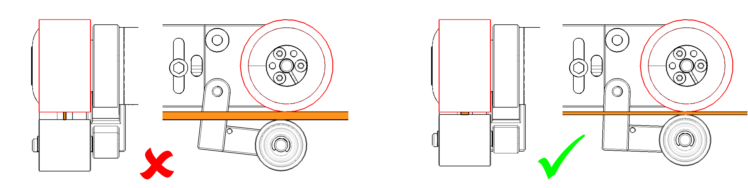
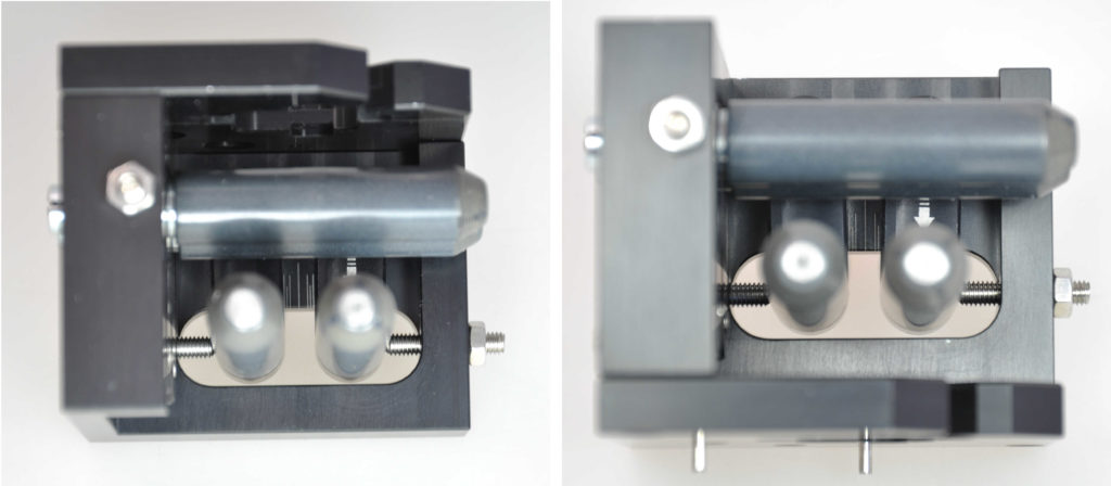
The wire should lay in it’s larger dimension on the encoder wheel. If the wire lays vertically with respect to the encoder wheel (as in the left image below) it tends more easily to make a torsion movement. This configuration is to avoid if possible.

-
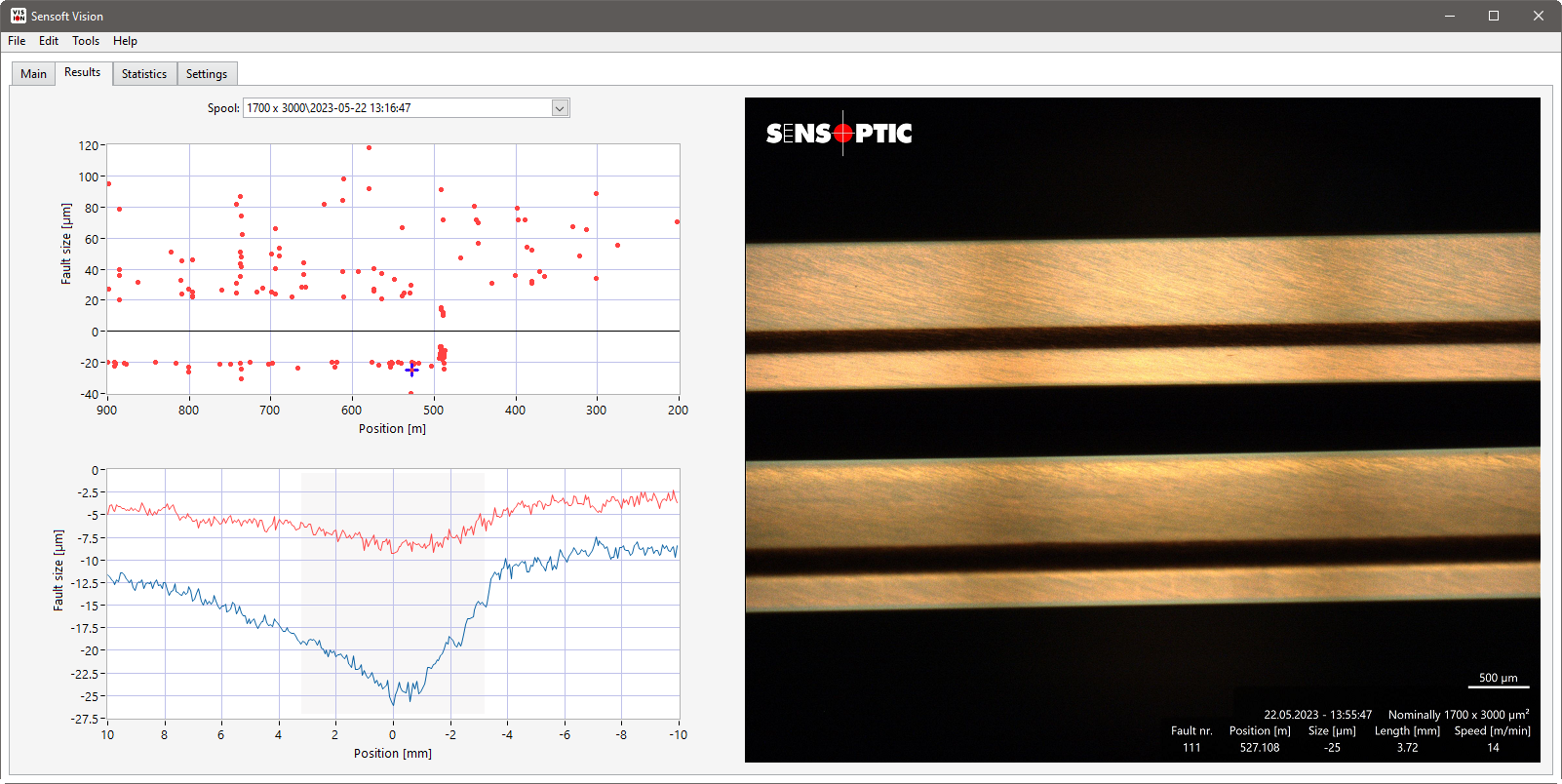
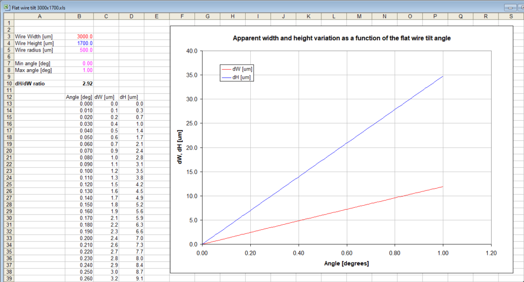
If the wire principal axes are aligned with the axes of the sensor X, Y, a torsion will increase the apparent dimensions. A decrease of the dimensions may indicate that the wire axes are not well aligned with the axes of the sensor. The next example shows this effect. In this case the wire was laying vertically with respect to the encoder: the part in contact with the encoder was the height of the wire and for this reason the axes are inverted (x and y). As explained in the previous point this configuration is to avoid.
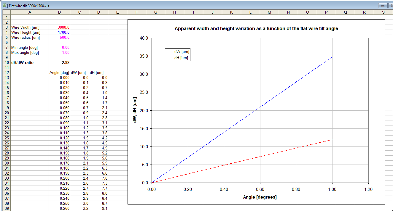
In this case the theoretical ratio for the wire dimensions of 1700 um x 3000 um and a radius of 500 is 2.92. The proportion between the X and Y graph has a similar ratio factor of about 3. In this case the wire axes are not well aligned with the axes of the sensor but have a misalignment of at least 0.7 degrees. If the axes of the wire are perfectly aligned with the axes of the sensor the effect of a torsion of the wire will be seen as a dimension increase and not as a decrease as in this case.

Here below there is a graph of the profiles of the previous fault n. 111 where the Y axis has been multiplied by a factor of 2.92. The shape of the profile being nearly the same it is most probable that this was not a real defect but an effect due to the torsion of the wire.