Definition of fault
Applies to
Sensoft Multiline
Sensoft Vision
Question
How is a fault measured exactly?
Answer
Sensystem measures changes in the wire diameter in a contactless, optical way. A LED illuminates the wire and the light behind the wire is recorded by a fast photodetector. Faults are detected by their change to the amount of shadow. We call the calibrated signal that is proportional to a swelling fault Lump signal, while the Neck-down signal indicates thinning faults.
Mono-axial sensors (like models PSM, MOQ, PXS) measure the lump signal in one direction and make it accessible to the software as is. Bi-axial sensors (like PXL and PSD) measure it in two orthogonal directions (LU x and LU y signals) and calculate a combined lump signal according to the equations to Figure 1.
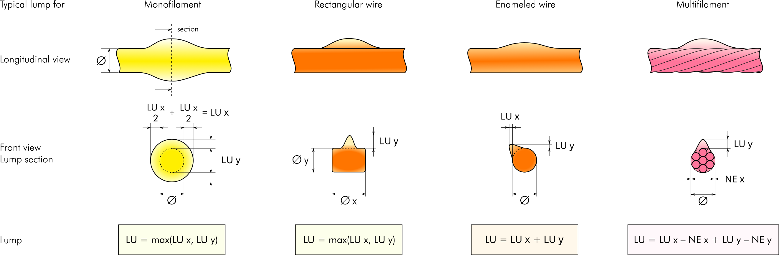
Figure 1: Calculation of lump signal for bi-axial sensors. The calculation depends on whether typical faults are axially symmetric or not, so that in both cases the resulting lump signal can be understood as the diameter change.
| Monofilament | LU = max(LU x, LU y, LU z) |
| Enameled wire | LU = max(LU x, LU y, LU z) |
| Multifilament | LU = (AC x + AC y + AC z)*2/Axes |
The equations for neck-down are similar, just exchange LU with NE in Figure 1. Note that rectangular wire should use the same setting as Monofilament. Beyond being more correct, it has also lower noise. Multifilament minimizes the lump and neck-down signals for twisted filaments, where the single-axis signals LU x and LU x oscillate. For 3-axial sensors (PXT) the calculation is performed according to Table 1. In Sensoft Vision the filament type is set on page Settings. In Sensoft Multiline it is determined by the calibration file selected in Hardware Configure dialog. Use a calibration file ending in "_M" for Monofilament and rectangular wire and a calibration file ending in "_W" for round Enameled wire. In Sensoft Multiline there is no Multifilament behavior.
The Fault size is the maximum signal during the fault. The Fault length is the length with signal above threshold, see Figure 2. A hysteresis prevents a noisy signal from generating fake faults, as is illustrated in Figure 3.
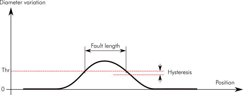
Figure 2: The Fault size is the maximum signal during the fault.The Fault length is the length with signal above threshold. The internal calculation uses a hysteresis to avoid problems with noisy signals (see Figure 3).
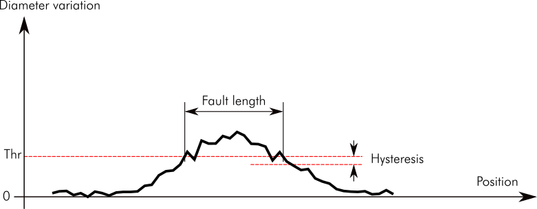
Figure 3: Without hysteresis a noisy signal could generate unwanted faults at the beginning or end of the fault. For example, the signal in this figure would, without hysteresis, generate three faults. To avoid this, the fault must cross Threshold minus Hysteresis to end. The Fault length is calculated from the first to the last time the signal crosses Threshold.